Common Defects in HVOF Coating and How to Avoid Them?
You want dense, tough HVOF coatings. Defects still show up, cause scrap, and hit delivery. I see this often. A calm, stepwise method helps stop the chaos.
Start with surface prep and powder condition, then verify powder feed and jet stability, confirm gun component consistency, and only then tune parameters. Track changes one by one to reduce variation and avoid new problems.

If you want fewer surprises, focus on stability first. I will walk through four symptoms I see most, show the defect chain behind them, and share what checks help. If you skim, you will miss links that matter. If you read through, you will find actions you can try today.
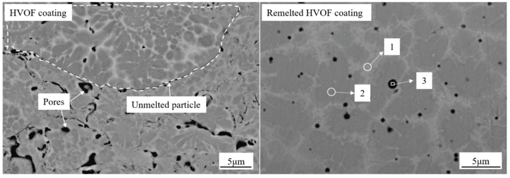
Porosity in HVOF Coatings: When “Dense” Is No Longer Dense?
You expect low porosity.1 You still see pores, sometimes only at certain hours or on certain parts. You change powder or blame the feeder. The root can be wider.
Reduce porosity by checking powder moisture and size consistency, stabilizing feed, confirming oxygen–fuel ratio and total flow, keeping spray distance consistent, and inspecting barrel condition. Small changes in jet energy and dwell time can open pores.2

Why porosity appears and where to look
I treat porosity as a stability problem. It can come from powder, feeding, flame, distance, or part heat. I start with simple checks, then move to deeper ones. I also include the gun barrel and combustion chamber because they can change the jet core and dwell time. I do not assign one cause. I build a short list and verify step by step. A European job shop once called me about a sudden porosity rise. The feeder looked fine on the screen, yet the barrel had a roughened bore. After a bore change and a feeder purge, the pores dropped. The powder did not change.
Quick map of contributors and checks
| Contributor | What can happen | What I check first |
|---|---|---|
| Powder moisture or satellites | Poor melting/flattening | Dry powder, sieve sample, microscope quick look |
| Feeder pulsing | Flow spikes, uneven deposit | Weigh catch test, hose kinks, wheel wear |
| Gas ratio or total flow drift | Underheating/overheating | Verify flows with calibrated meters |
| Spray distance drift | Dwell mismatch | Gauge standoff, program check |
| Barrel bore wear or roughness | Jet core instability | Bore roughness and straightness check |
| Combustion chamber throat wear | Flame shape shift | Visual plume, chamber dimension check |
Gun component consistency and porosity
Barrel internal finish can shift the jet core.3 A rough bore can disturb the boundary layer. That can change particle heating. A small change can raise porosity. Chamber throat erosion can affect the flame profile and particle dwell. I do not say this is the only cause. I say it can contribute. If parts came from different batches with different bore roughness, porosity can move. Matching bore finish and length helps reduce variation. I measure bore roughness and straightness on every run. I focus on repeatable dimensions because it helps process repeatability. It does not guarantee zero pores. It makes the jet behavior more stable.
Oxidation and Phase Decomposition: The Hidden Performance Killer?
You chose HVOF for low oxide. You still see dark streaks, hardness loss, or phase shift. Someone says the powder is bad. I look at oxygen, heat, and air leaks first.
Limit oxidation by keeping a stable, slightly fuel-rich flame4 when required, preventing air leaks, avoiding overheated barrels, managing standoff, and watching dwell time. Check powder morphology and surface area5, which can shift oxidation rate.

How oxygen and heat change the coating
Oxidation and phase changes come from oxygen potential, particle temperature, dwell time, and air entrainment. A small leak in gas seals can pull air into the plume.6 An eroded chamber can change the equivalence ratio even when setpoints are the same. A hot barrel can raise particle temperature. I once had a client see oxide spikes after swapping a “same model” chamber from a different supplier. Gas flows were unchanged. The throat diameter had drifted. The plume went leaner in practice. A chamber change with matched dimensions and a leak check dropped oxides again.
Sources and quick actions
| Source | Symptom in shop | Action that helps |
|---|---|---|
| Gas ratio drift | Plume color shift, oxide rise | Verify flow meters, re-zero controls |
| Air leaks at seals | Sooty edges, deposit browning | Soap-bubble check, replace O-rings |
| Barrel overheating | Dull plume, over-soft coating | Verify cooling, pause schedule |
| Excess dwell time | Oxide rim on splats | Reduce passes per layer, adjust traverse |
| Powder high surface area | Faster oxidation | Consider morphology change or fresh lot |
| Nozzle or chamber wear | Unstable jet | Dimensional check, replace with matched parts |
Component condition and phase stability
Combustion chamber throat size and roundness affect the flame.7 If the throat erodes, the flame speed and shape change. The actual oxygen potential at the particle changes. The powder can see more oxygen than expected. Barrel length or finish shifts the residence time. That can push phase changes in carbides or intermetallics. I do not state that parts alone explain every oxide. Process settings matter more. Yet I have seen how small, hidden part changes add variation. This is why I check chamber and barrel dimensions before I adjust parameters. A stable jet makes parameter tuning effective. It also makes results more repeatable across shifts and jobs.
Poor Adhesion Strength: It Starts Before Spraying?
Pull tests fail. Edges peel. You increase bond coat passes. It helps one day and fails the next. I do not start with more spray. I start with the surface.
Raise adhesion by controlling blast profile and cleanliness, minimizing time from blast to spray8, keeping the jet stable, and using small, consistent first passes. Confirm bond coat choice and angles before adjusting heat.

Not all adhesion loss is a bond coat problem
Adhesion depends on mechanical keying, impact energy, and cleanliness.9 Oil film, moisture, or low roughness can kill adhesion. A wide jet with low particle velocity can also weaken the first contact. I ask for the blast profile first. I ask how long the part waits after blasting. I ask about shop humidity. I then look at angle and distance. I recall a case where adhesion failed on Mondays. The team blasted on Friday and sprayed on Monday. A small dew point swing was enough to condense a thin film. They moved blasting to the same day. Pull-off values went back up.
Adhesion checks and small fixes
| Area | What I look for | Why it matters | Small fix |
|---|---|---|---|
| Blast roughness | Ra/Rz consistent | Mechanical key | Verify media size, worn media |
| Cleanliness | No oil, no dust | Bonding area | Solvent wipe, white cloth test |
| Time to spray | Short window | Avoid oxide/moisture | Blast and spray same shift |
| Angle and standoff | Near normal, stable | Impact energy | Adjust fixturing, teach path |
| First passes | Thin, cool | Avoid debond layer | Use light wetting pass |
| Jet stability | Tight core | Particle velocity | Check barrel/chamber condition |
Jet stability and bond strength
A consistent jet core helps particle velocity and flattening.10 If the jet wanders or broadens, impact energy drops. The first passes are the most sensitive. Inconsistent barrels can change jet width and shock structure. That can shift adhesion. I have seen two barrels from different batches give different bond strength even with the same settings. It does not mean the barrel caused failure alone. It means it added variation. I now match bore dimensions and finish. I run a simple coupon with a known bond coat to confirm whether the jet is stable before any job that is critical. This makes later parameter tweaks work better.
Residual Stress and Cracking: The Thermal Mismatch Problem?
You hit thickness. The part cools. Cracks show up at edges or across flats. You check hardness and porosity. Both look fine. Stress did the damage.
Control residual stress by managing heat input and dwell, limiting layer thickness per pass11, keeping substrate temperature steady, watching geometry, and balancing particle temperature and velocity. Check component consistency that can swing particle energy.

Stress comes from heat, mismatch, and impact
Residual stress builds from thermal gradients and the difference in expansion between coating and substrate. Impact peening adds compressive stress.12 Overheating lowers it. Sharp geometry concentrates stress. I start by measuring part temperature during spray. I limit dwell and allow even cooling. I split thick builds into more, thinner layers. I also review powder choice for CTE. I saw a turbine part crack after a process change that aimed to speed up. The team increased passes per layer and reduced cooling breaks. The crack frequency matched corners with high heat load. They went back to thinner layers and breaks. Cracks dropped.
Stress map and control levers
| Source | Sign in shop | Action that helps |
|---|---|---|
| High heat input | Edge cracking after cooldown | Shorter passes, more breaks |
| Low particle velocity | Brittle splats, low peening | Stabilize jet, adjust ratio modestly |
| Thick layers per pass | Mud-crack pattern | Thinner layers, more cycles |
| Sharp geometry | Cracks at corners | Mask edges, tailor path |
| CTE mismatch | Early service cracks | Review powder or bond coat |
| Uneven cooling | Side-to-side distortion | Balanced path, airflow control |
Component consistency and stress balance
Particle impact energy sets the balance between peening and bonding. If barrels vary in length or bore finish, particle velocity can shift. A small change can raise tensile stress in the layer. Combustion chamber wear can also change the heat input without a visible change in settings. I do not say parts cause every crack. I say they can contribute. I treat parts as a quality-risk decision. Cheap parts can work. If they vary in shape or finish, the process can vary more. I aim for consistent dimensions and surface finish so the jet stays stable. This helps the team control heat and velocity and keep stress in a safer window.
Conclusion
Treat defects as system signals. Check surface prep, powder, feed, jet, and parts. Stabilize first. Then tune. Small, consistent changes reduce variation and protect delivery.
"[PDF] Microstructure and Properties of HVOF-Sprayed Protective Coatings", https://inldigitallibrary.inl.gov/sites/sti/sti/4045032.pdf. Peer‑reviewed reviews of HVOF spraying report that the process routinely yields dense coatings with porosity often below about 1–2%, lower than many air plasma-sprayed counterparts, supporting the expectation of low porosity for HVOF coatings. Evidence role: expert_consensus; source type: paper. Supports: That HVOF typically produces dense coatings with low porosity relative to conventional thermal spray processes.. Scope note: Porosity depends on material, powder characteristics, and specific parameters, so values vary by system. ↩
"An Influence of Oxygen Flow Rate and Spray Distance on the ... - PMC", https://pmc.ncbi.nlm.nih.gov/articles/PMC9505576/. Experimental studies in thermal spray literature show that changes in fuel–oxygen ratio, total flow, and stand‑off distance alter particle temperature/velocity and residence time, which correlate with porosity changes in HVOF deposits. Evidence role: mechanism; source type: paper. Supports: That porosity in HVOF coatings is sensitive to jet energy (e.g., gas ratio/flow) and particle residence/dwell time through their impact on particle heating and flattening.. Scope note: Specific sensitivities are material‑ and hardware‑dependent. ↩
"Warm spraying—a novel coating process based on high-velocity ...", https://pmc.ncbi.nlm.nih.gov/articles/PMC5099653/. Studies on HVOF nozzle erosion report measurable shifts in gas/particle velocity and temperature with wear or dimensional change, which in turn influence deposit density and porosity. Evidence role: mechanism; source type: paper. Supports: That nozzle/barrel wear or surface condition changes gas dynamics and particle velocity/temperature in HVOF, thereby affecting porosity.. Scope note: Direct data on ‘surface finish’ per se are less common than on geometric wear, but both affect internal flow conditions. ↩
"Modeling and control of HVOF thermal spray processing of ...", http://pdclab.seas.ucla.edu/Publications/MLi/MLi_DShi_PDChristofides_PowderTech_2005_156_Modeling_Control_HVOF_Thermal_Spray.pdf. HVOF studies show that lowering the effective oxygen potential by operating fuel‑rich reduces oxide formation in carbide and metallic coatings compared with stoichiometric or oxidizing conditions. Evidence role: mechanism; source type: paper. Supports: That operating at fuel‑rich conditions reduces oxide formation in materials sensitive to oxidation during HVOF spraying.. Scope note: Optimal richness depends on material system and must be balanced against other properties (e.g., decarburization, deposition efficiency). ↩
"[PDF] Oxidation in Reused Powder Bed Fusion Additive Manufacturing Ti ...", https://tsapps.nist.gov/publication/get_pdf.cfm?pub_id=932159. Materials studies show that increased specific surface area and fine particle fractions raise oxidation rates during thermal spraying due to higher surface reactivity and faster oxygen uptake. Evidence role: mechanism; source type: paper. Supports: That powders with higher specific surface area or fine satellites tend to oxidize faster during flight/heating in HVOF.. Scope note: Effects vary with alloy/carbide chemistry and carrier gas environment. ↩
"[PDF] High Temperature Corrosion Behavior of HVOF, Fe3Al Coatings", https://netl.doe.gov/sites/default/files/event-proceedings/2012/26th%20Annual%20Conference%20on%20Fossil%20Energy%20Materials/Manu/FE_Materials_26th_Conference_Lillo_Hi_Temp_Corrosion_Behavio.pdf. Educational and research texts on thermal spray physics explain that air entrainment into high‑velocity jets elevates local oxygen availability around particles, which promotes oxidation when leaks or poor sealing allow mixing. Evidence role: mechanism; source type: education. Supports: That air entrainment into the HVOF jet increases the oxygen available for particle oxidation.. Scope note: Direct shop leak case studies are limited; most references infer from jet mixing and oxidation kinetics. ↩
"[PDF] Design and Development of a High Velocity Oxy-Fuel Thermal ...", https://scholarworks.utep.edu/cgi/viewcontent.cgi?article=2209&context=open_etd. Experimental measurements and flow/particle simulations indicate that HVOF nozzle and chamber throat geometry strongly influence gas velocity, mixing, and particle temperature/velocity, thereby affecting oxidation behavior. Evidence role: mechanism; source type: research. Supports: That HVOF chamber/nozzle throat geometry affects gas flow, mixing, and particle thermal histories.. Scope note: Most data are for specific gun designs; extrapolation to all models requires caution. ↩
"[PDF] THERMAL SPRAYED COATINGS (METALLIZATION) PROGRAM", https://connect.ncdot.gov/resources/Materials/MaterialsResources/Thermal%20Sprayed%20Coatings%20(Metalization)%20Program.pdf. Thermal spray and corrosion‑control standards advise coating promptly after surface preparation to avoid moisture and oxide formation that degrade adhesion of subsequently applied coatings. Evidence role: expert_consensus; source type: institution. Supports: That best‑practice standards recommend coating soon after blasting to prevent contamination and oxidation that reduce adhesion.. Scope note: Exact allowable time windows depend on environment and material; documents provide guidance rather than a single universal limit. ↩
"Thermal spraying - Wikipedia", https://en.wikipedia.org/wiki/Thermal_spraying. Authoritative handbooks and standards on thermal spraying describe adhesion as dominated by mechanical interlocking aided by adequate particle impact/flattening and clean, properly prepared substrates. Evidence role: expert_consensus; source type: institution. Supports: That mechanical interlocking (roughness), particle impact conditions, and cleanliness are primary contributors to thermal spray adhesion strength.. Scope note: The relative contribution of each factor varies by coating/substrate system and bond coat use. ↩
"[PDF] Modeling and Control of an Industrial High Velocity Oxygen-Fuel ...", http://pdclab.seas.ucla.edu/pchristo/pdf/LSC_SCNC7talk.pdf. Foundational texts on thermal spray explain that adequate and consistent particle velocity/temperature are critical for splat flattening and bonding, and that stable jets reduce variability in these particle states. Evidence role: mechanism; source type: education. Supports: That particle velocity and temperature distributions control splat flattening and bonding, and that stable jets improve consistency of these particle states.. Scope note: Direct measurements of ‘jet core stability’ are indirect; most evidence uses particle diagnostics as proxies. ↩
"Effect of Deposition Rate and Deposition Temperature on Residual ...", https://ui.adsabs.harvard.edu/abs/2020JTST...29.1322V/abstract. Residual stress studies in thermal spray show that increased heat input and thick per‑pass deposition elevate tensile stress and cracking propensity, while thinner, staged layers reduce stress accumulation. Evidence role: mechanism; source type: paper. Supports: That higher per‑pass thickness and heat input increase tensile residual stress and mud‑cracking risk, whereas thinner layers with cooling breaks mitigate it.. Scope note: Optimal pass thickness is system‑specific and influenced by substrate geometry and cooling. ↩
"Residual Stresses | Center for Thermal Spray Research", https://www.stonybrook.edu/commcms/ctsr/research/_publications/Residual%20Stress.php. Reviews on residual stresses in thermal spray coatings identify a peening component from high‑velocity particle impacts that can introduce compressive stresses, counteracting thermally induced tensile stresses to some degree. Evidence role: mechanism; source type: paper. Supports: That in thermal spray, shot‑peening‑like effects from high‑velocity particle impacts contribute to compressive residual stresses in addition to thermal stresses.. Scope note: Magnitude and sign of net stress depend on process parameters and material; the peening contribution is not always dominant. ↩