I often see one costly mistake: people expect a thermal barrier coating to save efficiency by insulation alone, then they miss the real control points.
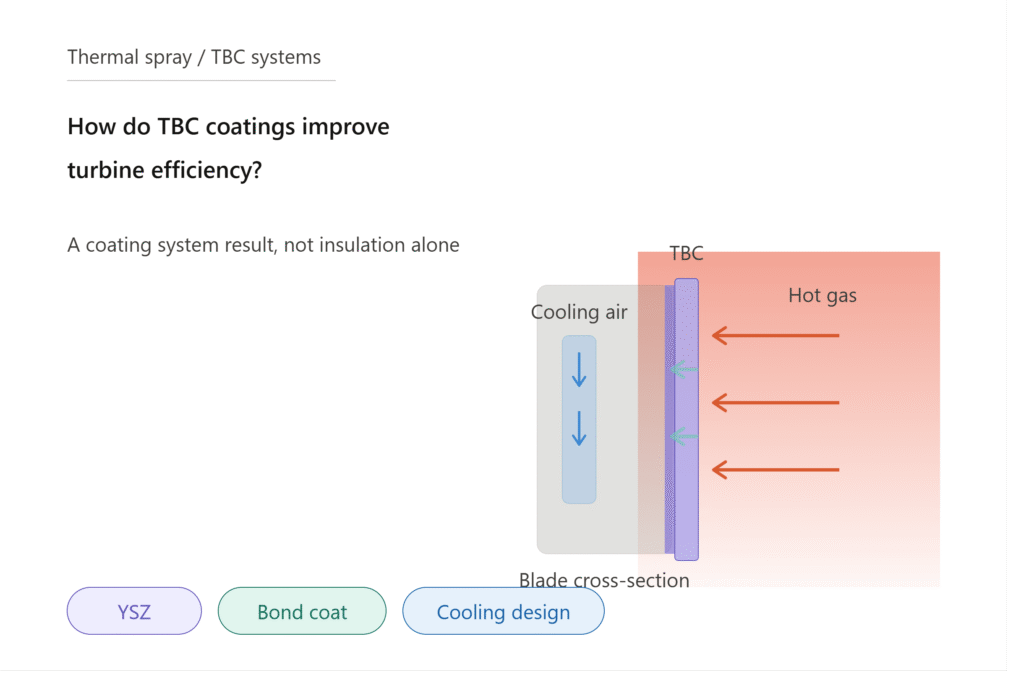
I see TBC coatings improve turbine efficiency when they help hot-section parts survive higher gas temperatures or need less cooling air1. I treat this as a design and process result, not an automatic coating benefit. The coating system, spray quality, and service conditions must all support the target.

I work around thermal spray guns, consumables, and process stability every day. I have learned that a coating can look correct on paper, yet still fail to support the real turbine goal. I care about the coating structure, the interface, the gun condition, and the repeatability of the whole spray process.
Do TBCs Improve Turbine Efficiency by Supporting Higher Operating Temperatures—Not Simply by “Insulating Better”?
I hear the phrase “better insulation” too often. It sounds simple, but it can lead a service team to ignore turbine design, cooling air, and real operating limits.
I understand TBCs as a way to protect turbine hot-section components from high gas temperature, so the engine or turbine may run in a hotter or lower-cooling-loss window. I do not treat insulation value alone as proof of better efficiency.

I look at TBCs through the working condition of the turbine. A gas turbine gets more useful energy when the hot gas path is designed to operate at higher temperature and with well-managed cooling2. A TBC can help because it reduces the heat reaching the metal surface. This can protect blades, vanes, combustor parts, and other hot-section components. I still do not say that the coating alone creates efficiency. The turbine must be designed or operated to use the thermal margin.
How I Explain the Efficiency Mechanism
| Item I Check | What It Means for Efficiency | Why I Stay Careful |
|---|---|---|
| Turbine inlet temperature | A higher allowed gas temperature may improve cycle performance3 | The turbine design must allow it |
| Cooling air demand | Less cooling air may reduce performance loss4 | Cooling design must be validated |
| Metal temperature | Lower metal temperature can protect the part | The sensor data and life model matter |
| Coating durability | Stable coating can hold the thermal benefit longer | Spallation can remove the benefit |
| Operating profile | Steady operation and cycling change risk | Field conditions are rarely ideal |
I explain this point to customers in a practical way. If the turbine cannot use a higher temperature window, the TBC may still improve part protection, but the efficiency gain may be small or indirect. If the cooling strategy is unchanged, the main benefit may be longer component life. If cooling air can be reduced safely, the benefit may be stronger. I also pay attention to local hot spots. A coating with uneven thickness or poor structure can create weak areas. I have seen spray process drift change the coating condition even when the powder name stayed the same. That is why I connect the thermodynamic idea to the shop-floor reality. The efficiency story starts in turbine design, but it can be lost during coating production.
Is a Thermal Barrier Coating a System, Not Just a Ceramic Layer?
I see many people talk only about the top coat. That view is risky because a TBC fails or succeeds through the whole stack and every interface.
I define a TBC as a coating system that includes the ceramic top coat, bond coat, substrate, oxide growth, porosity, thickness, surface preparation, and thermal cycling behavior. I do not judge it by ceramic material alone.

I usually start with the ceramic top coat because it is the visible thermal barrier. Many systems use yttria-stabilized zirconia, often called YSZ, because it has low thermal conductivity and good thermal cycling behavior in many turbine uses5. I still do not stop there. The bond coat is just as important. It helps adhesion and oxidation resistance. Common bond coat families include MCrAlY and aluminide-type coatings6. The substrate also matters because it expands, oxidizes, and carries load under heat.
What I Include in a Real TBC System Review
| Part of the System | What I Look For | What Can Go Wrong |
|---|---|---|
| Substrate | Clean surface, correct roughness, no hidden damage | Poor adhesion or early cracking |
| Bond coat | Oxidation resistance and stable interface | Fast oxide growth or weak bonding |
| Thermally grown oxide | Slow and uniform growth | Stress build-up and spallation |
| Ceramic top coat | Correct porosity, thickness, and microstructure | Too dense, too weak, or uneven |
| Interfaces | Clean contact and controlled stress | Delamination under cycling |
| Service environment | Temperature, deposits, fuel quality, cycling | Hot corrosion, erosion, or CMAS attack |
I pay special attention to the interface between layers. A coating can pass a simple thickness check and still have poor long-term behavior. Thermal cycling is one reason. The metal and ceramic expand at different rates. The bond coat oxidizes. The oxide layer grows. Stress builds.7 If the system was not designed well, the ceramic can crack or spall. After spallation, the protected metal can see much higher heat. The turbine may then lose the benefit that the coating was meant to support.
I also treat porosity as a controlled feature, not a defect by default. In many air plasma sprayed TBCs, porosity helps reduce thermal conductivity and can help strain tolerance8. Too much porosity can weaken the coating. Too little porosity can make the coating too stiff. Electron beam physical vapor deposition, often called EB-PVD, can create a columnar structure with strong strain tolerance for some blade uses9. Air plasma spray, often called APS, can create a lamellar structure. Each route has strengths. I do not choose a process only by name. I choose it by part geometry, service condition, cost, repair plan, and validated coating performance.
Why Does Process Consistency Matter as Much as Material Selection?
I have seen a correct material choice lose its value when the spray process is unstable. The powder was not the only cause. The process made the structure.
I treat process consistency as a core part of TBC performance because spray parameters, gun stability, consumable wear, powder feed, and part handling all shape coating structure and durability.

My daily work is close to thermal spray equipment and wear parts. I manufacture spray guns and consumables, so I see how small changes in hardware condition can affect the process. I do not claim that my shop measures turbine efficiency. I do know that coating repeatability depends on stable arcs, stable gas flow, correct powder injection, and consistent torch behavior10. If the spray gun drifts, the coating can drift. If an electrode or nozzle wears unevenly, the plasma jet can change. If the barrel or gun body is not stable, heat transfer and particle behavior can change.
Process Variables I Watch Closely
| Process Area | What I Check | What It Can Change in the Coating |
|---|---|---|
| Spray gun condition | Arc stability, cooling, alignment, wear | Particle temperature and velocity |
| Electrodes and nozzles | Erosion, geometry, material consistency | Plasma jet shape and heat input |
| Powder feed | Feed rate, carrier gas, injection position | Deposition rate and unmelted particles |
| Robot path | Stand-off distance, angle, overlap | Thickness uniformity and roughness |
| Part preparation | Grit blast quality and cleanliness | Adhesion and interface quality |
| Environmental control | Humidity, contamination, shop discipline | Oxides and repeatability |
I also care about consumable consistency because the spray process is not only a recipe in a control panel. The arc attaches to real parts. Gas flows through real passages. Cooling channels carry heat away from real gun bodies. If the consumables are not repeatable, the same set point may not create the same plasma condition. This is one reason I take precision machining seriously. In our own work, we focus on tight dimensions, bore quality, and stable tungsten-copper joining for electrodes and related parts. I connect this to coating quality in a direct way. Stable hardware helps the coating provider hold a stable process window.
I have also seen teams focus on coupon results, then forget production geometry. A flat coupon is useful, but a real blade or vane has edges, curves, holes, and shadowed zones. The coating can become too thick in one area and too thin in another. The microstructure can change across the part. A service provider needs process control, fixture control, and inspection control. Material selection matters. I still believe repeatability is where many real coating problems start or stop.
Under What Conditions Can TBCs Deliver Reliable Efficiency Benefits?
I do not like simple promises. A TBC can support efficiency, but it can also become only a cost if the design and process are not controlled.
I believe TBCs deliver reliable efficiency benefits when the turbine design uses the thermal margin, the coating system is validated, the spray process is repeatable, and service conditions stay within the intended window.

I ask a practical question before I talk about efficiency: what change will the turbine owner actually make because of the TBC? If the answer is “nothing,” then the efficiency claim needs care. The coating may still protect parts. It may help with maintenance intervals. It may reduce risk in hot areas. But the efficiency benefit usually needs a design or operating action. That action may be higher firing temperature, lower cooling air use, improved hot-section durability, or more stable operation over time. Each one needs engineering validation.
Conditions I Would Want Before I Trust the Efficiency Story
| Condition | My Practical Question | Why It Matters |
|---|---|---|
| Turbine design link | Does the design use the coating margin? | The coating alone does not change the cycle |
| Cooling strategy | Can cooling air be reduced safely? | Cooling air affects useful work |
| Coating specification | Is thickness, porosity, and bond coat controlled? | Structure controls thermal behavior |
| Process qualification | Are coupons and real parts both checked? | Production parts are harder than coupons |
| Service profile | How many starts, stops, and heat cycles occur? | Cycling drives cracks and spallation |
| Inspection plan | How will damage be found before failure? | Lost coating means lost protection |
| Repair plan | Can the part be stripped and recoated correctly? | Poor repair can shorten life |
I also look at failure modes because reliable efficiency depends on coating survival. A TBC can suffer from spallation, erosion, oxidation, hot corrosion, and deposit-related attack. In some turbines, calcium-magnesium-alumino-silicate deposits, often called CMAS, can melt and damage ceramic coatings11. I do not use these risks to scare people. I use them to set realistic requirements. A coating that survives a lab test may still face harder field conditions. Fuel quality, dust, salt, operating cycles, and maintenance practices can all affect results.
I also advise service providers to explain TBC value with careful language. I would say, “This coating system may support higher temperature capability or reduced cooling demand when the turbine design and validation allow it.” I would avoid saying, “This coating will improve efficiency.” That second sentence sounds strong, but it skips too many conditions. It can also create false expectations with the end user.
I think the best commercial conversation is clear and technical. The customer should know what the coating can do. The customer should also know what it cannot do alone. The coating cannot rewrite the turbine cycle. The coating cannot fix poor cooling design. The coating cannot survive bad process control forever. But a well-designed and well-sprayed TBC system can become part of a stronger hot-section strategy. That is the real reason TBCs matter for turbine efficiency.
Conclusion
I see TBC efficiency value as a controlled system result: right design, right coating stack, stable spray process, and suitable service conditions working together.
"[PDF] 4.2.1-1 Introduction Cooling Design Analysis Ron S. Bunker", https://www.netl.doe.gov/sites/default/files/gas-turbine-handbook/4-2-1.pdf. Research demonstrates that thermal barrier coatings enable efficiency improvements through two primary mechanisms: allowing higher turbine inlet temperatures and reducing parasitic cooling air requirements. Evidence role: mechanism; source type: research. Supports: TBC coatings improve turbine efficiency when they help hot-section parts survive higher gas temperatures or need less cooling air. Scope note: Efficiency gains depend on turbine design modifications to utilize the thermal protection provided by the coating system. ↩
"Brayton cycle - Wikipedia", https://en.wikipedia.org/wiki/Brayton_cycle. Gas turbine thermodynamic analysis confirms that cycle efficiency increases with higher turbine inlet temperature according to Brayton cycle principles, while excessive cooling air reduces net work output. Evidence role: mechanism; source type: education. Supports: A gas turbine gets more useful energy when the hot gas path is designed to operate at higher temperature and with well-managed cooling. Scope note: Efficiency gains are constrained by material temperature limits and cooling system design requirements. ↩
"3.7 Brayton Cycle - MIT", https://web.mit.edu/16.unified/www/FALL/thermodynamics/notes/node28.html. Thermodynamic analysis shows that gas turbine cycle efficiency increases approximately 0.5-1% for every 10°C increase in turbine inlet temperature, following Brayton cycle principles. Evidence role: mechanism; source type: education. Supports: A higher allowed gas temperature may improve cycle performance. Scope note: Actual performance gains depend on turbine design constraints, cooling requirements, and material temperature limits. ↩
"[PDF] 4.2.1-1 Introduction Cooling Design Analysis Ron S. Bunker", https://www.netl.doe.gov/sites/default/files/gas-turbine-handbook/4-2-1.pdf. Turbine performance analysis indicates that reducing cooling air extraction by 1% of compressor flow can improve cycle efficiency by approximately 0.2-0.4%, depending on turbine design and operating conditions. Evidence role: mechanism; source type: research. Supports: Less cooling air may reduce performance loss. Scope note: Cooling air reduction must maintain acceptable metal temperatures and component life requirements. ↩
"[PDF] Syntactic YSZ TBC for improved thermal resistance of turbine ...", https://www.netl.doe.gov/sites/default/files/event-proceedings/2012/univ%20turbine%20workshop/Grogan.pdf. Materials research confirms that yttria-stabilized zirconia exhibits thermal conductivity values of 1-2 W/mK and demonstrates superior thermal shock resistance compared to other ceramic coating materials. Evidence role: general_support; source type: paper. Supports: Many systems use yttria-stabilized zirconia, often called YSZ, because it has low thermal conductivity and good thermal cycling behavior in many turbine uses. Scope note: Performance characteristics vary with YSZ composition, microstructure, and specific operating conditions. ↩
"[PDF] An Alternative Low-Cost Process for Deposition of MCrAlY Bond ...", https://www.netl.doe.gov/sites/default/files/2017-12/Bates-TNTech-UTSR-2011.pdf. Technical literature identifies MCrAlY (metal-chromium-aluminum-yttrium) and aluminide coatings as the primary bond coat systems used in thermal barrier coating applications for oxidation resistance and adhesion. Evidence role: definition; source type: encyclopedia. Supports: Common bond coat families include MCrAlY and aluminide-type coatings. Scope note: Selection depends on substrate material, operating temperature, and specific service requirements. ↩
"Residual Stresses Modeled in Thermal Barrier Coatings", https://ntrs.nasa.gov/citations/20050177176. Finite element analysis and experimental studies confirm that thermal cycling generates stress concentrations at TBC interfaces due to coefficient of thermal expansion mismatch and thermally grown oxide thickening. Evidence role: mechanism; source type: paper. Supports: Thermal cycling creates stress buildup in TBC systems due to differential expansion and oxide growth. Scope note: Stress levels and failure modes vary with coating system design, thermal cycle parameters, and substrate geometry. ↩
"Characterization of thermal barrier coatings with a gradient in porosity", https://www.academia.edu/9047704/Characterization_of_thermal_barrier_coatings_with_a_gradient_in_porosity. Microstructural studies demonstrate that controlled porosity in air plasma sprayed thermal barrier coatings reduces thermal conductivity by 30-50% and provides compliance to accommodate thermal expansion mismatch. Evidence role: mechanism; source type: paper. Supports: In many air plasma sprayed TBCs, porosity helps reduce thermal conductivity and can help strain tolerance. Scope note: Optimal porosity levels depend on specific coating composition and service conditions, with excessive porosity reducing mechanical strength. ↩
"Microstructure Dependence of Effective Thermal Conductivity of EB ...", https://pmc.ncbi.nlm.nih.gov/articles/PMC8067972/. Research shows that EB-PVD thermal barrier coatings develop columnar grain structures that provide superior strain tolerance through inter-columnar gaps that accommodate thermal expansion stresses. Evidence role: mechanism; source type: paper. Supports: Electron beam physical vapor deposition, often called EB-PVD, can create a columnar structure with strong strain tolerance for some blade uses. Scope note: EB-PVD coatings are primarily used on rotating components where strain tolerance is critical, with higher processing costs than plasma spray methods. ↩
"[PDF] PLASMA SPRAY COATINGS FOR POLYMER COMPOSITES - SOAR", https://soar.wichita.edu/bitstreams/373958b8-8578-4f38-b11e-97957c7e3c78/download. Process studies demonstrate that thermal spray coating properties are directly influenced by plasma arc stability, gas flow consistency, powder feed rate control, and torch hardware condition. Evidence role: mechanism; source type: research. Supports: TBC coating quality depends on stable arcs, stable gas flow, correct powder injection, and consistent torch behavior. Scope note: Optimal parameter windows vary with specific coating materials, substrate geometry, and equipment design. ↩
"[PDF] GT2017-64051 - NASA Technical Reports Server (NTRS)", https://ntrs.nasa.gov/api/citations/20170008019/downloads/20170008019.pdf. Studies demonstrate that CMAS deposits melt at temperatures above 1200°C and infiltrate thermal barrier coating porosity, causing chemical reaction and mechanical damage upon cooling. Evidence role: mechanism; source type: paper. Supports: calcium-magnesium-alumino-silicate deposits, often called CMAS, can melt and damage ceramic coatings. Scope note: CMAS attack severity depends on deposit composition, operating temperature, and coating microstructure characteristics. ↩