Combustion Chamber Failure Analysis: What Should I Check First?
I see teams lose coating time after chamber cracks, burn marks, or short life appear. I also see the real cause get missed too fast.
I start combustion chamber failure analysis by checking visible damage, critical dimensions, bore surface quality, fit, process settings, cooling, and maintenance history together. I do not treat every failed chamber as a material problem, because machining, geometry, surface finish, and operating conditions may all affect stability and service life.1
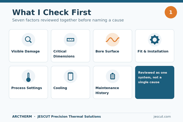
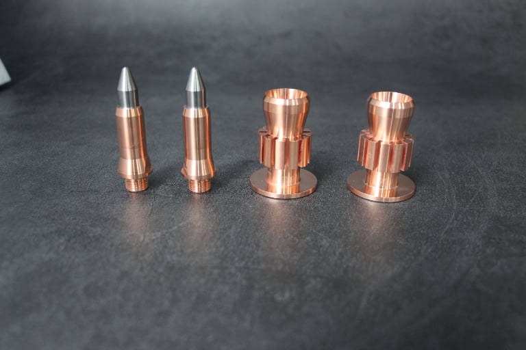
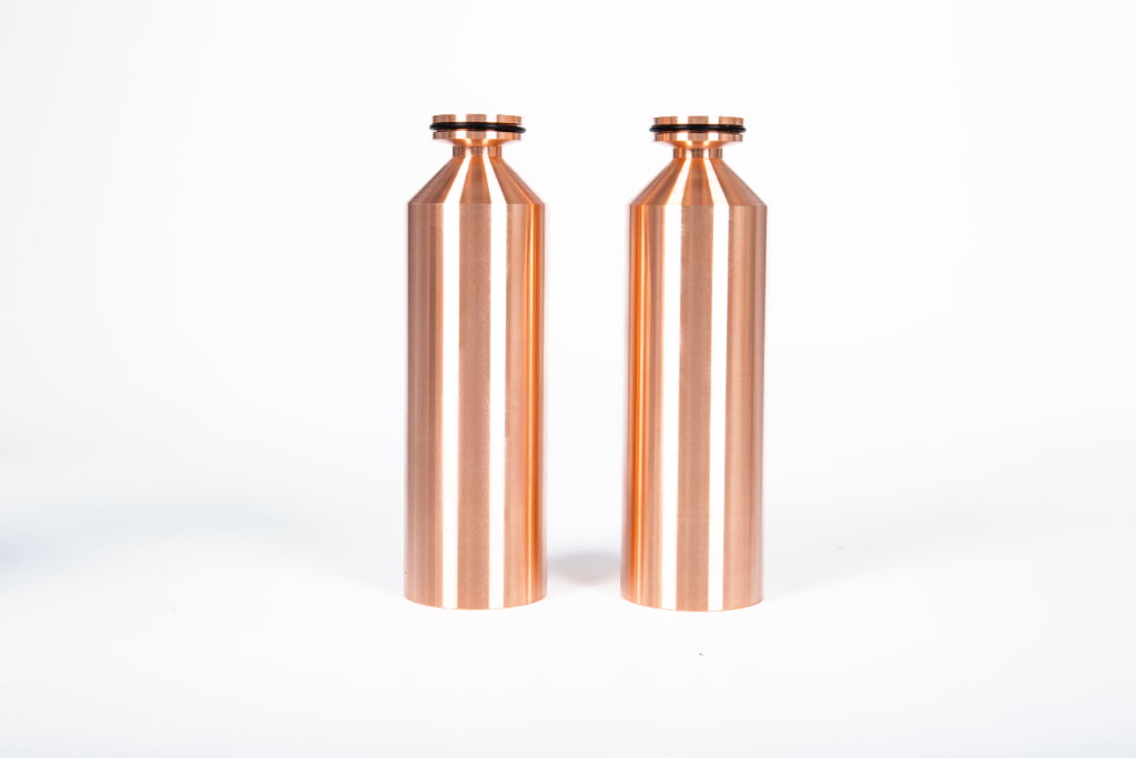
I have worked with thermal spray combustion chambers and related consumables for many years. In my daily work, I do not see failure as one isolated event. I see it as the final result of many small details. A chamber may look simple from the outside. It may also match the same gun model. But the real performance depends on the inside bore, the shape, the key dimensions, the fit, and the process environment.
I write this article from a manufacturing view. I focus on what I can inspect and control during production. I look at machining accuracy, inner-bore roughness, geometric consistency, and surface quality. I also respect the field side. I know that installation, cooling, fuel and oxygen settings, powder behavior, and cleaning habits may also affect the chamber.
So I do not ask one narrow question, such as “Was the material bad?” I ask a better question: “Which controlled factor changed, and how did that change affect heat, flame, flow, and life?”
Common Signs of Combustion Chamber Degradation: What Operators Usually Observe First?
I often hear the same first report from the workshop. The chamber looks burned, cracked, rough, or unstable, and production cannot continue with confidence.
A degraded combustion chamber may show cracks, erosion, burn-through marks, local overheating, abnormal discoloration, unstable flame behavior, or shorter service life.2 I treat these signs as symptoms. I then check material condition, machining quality, fit, cooling, process settings, and maintenance records before I decide the likely cause.
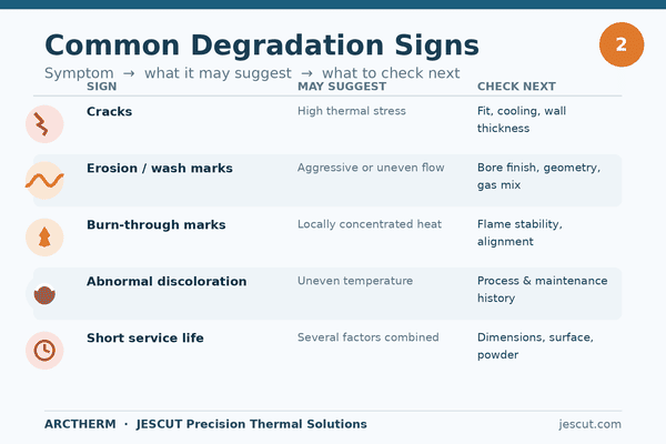
I usually begin with the visible signs because they tell me where to look next. I do not stop at the first mark. A crack may come from heat stress, but the stress may connect to fit, cooling, or wall thickness.3 A burn mark may point to local overheating, but the heat pattern may connect to flame position, flow path, or bore surface condition.4 Short service life may seem like a material issue, but it may also connect to unstable operation or poor geometric consistency.
How I read the first symptoms
| Visible sign I see | What it may suggest | What I check next |
|---|---|---|
| Cracks near high-heat area | Thermal stress may be high | Fit, cooling, wall thickness, heat path |
| Erosion or wash marks | Flow may be aggressive or uneven | Bore finish, geometry, fuel/oxygen setting |
| Burn-through marks | Heat may be concentrated locally | Flame stability, chamber alignment, cooling |
| Abnormal color | Temperature may be uneven | Process history and maintenance |
| Short life | Several factors may combine | Dimensions, surface quality, settings, powder |
I like to separate symptom and cause. This keeps the discussion fair. It also helps procurement teams avoid a simple but risky judgment. If a chamber fails early, I want to compare the failed part with the original drawing, the process condition, and the actual installation condition. I want to know if the key dimensions stayed stable. I want to know if the inner bore was smooth enough. I want to know if the flame path had a clean shape. I want to know if the chamber worked under normal settings or under a changed process.
In my manufacturing review, I pay close attention to repeatability. One chamber can pass a simple fit check, but another chamber from the same batch may not behave the same if machining is unstable. That is why I do not only inspect the outside. I inspect the controlled surfaces and the key zones that affect flow and heat. I do this because the first visible sign is only the start of the analysis.
How Machining Precision and Inner-Bore Surface Quality Influence Chamber Stability?
I have seen small machining differences create large process questions. A chamber can look correct, but the flame can still behave in a less stable way.
Machining precision and inner-bore surface quality may influence chamber stability because they affect fit, flow direction, heat distribution, and flame behavior.5 I check critical dimensions, bore roughness, concentricity, and surface marks because small errors may create local heat concentration or unstable combustion conditions.
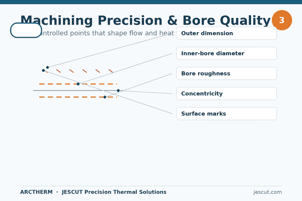
In my factory work, I treat a combustion chamber as a precision part, not just a replaceable metal part. The inner bore is especially important. The gas path and heat path pass through this area. If the bore surface is rough, scratched, or uneven, the flow may be disturbed.6 If the geometry is not consistent, the flame position may shift.7 If the fit area is not controlled, the chamber may not sit in the correct position.
Manufacturing points I pay attention to
| Controlled point | Why I check it | Possible effect if unstable |
|---|---|---|
| Key outside dimensions | I need correct fit in the gun body | Poor alignment or sealing risk |
| Inner-bore diameter | I need stable flow area | Flow change and heat change |
| Bore roughness | I need smooth gas and flame path | Local turbulence or deposit risk |
| Concentricity | I need stable flame direction | Uneven heating or off-center wear |
| Surface machining marks | I need clean thermal behavior | Hot spots may develop |
I often explain this with a simple example. If two chambers have the same part number, I still ask if the inner bore has the same quality. A drawing dimension alone does not show every surface condition. The tool path, tool wear, clamping method, and final finishing step can change the surface. These changes may be small to the eye. They may still matter when the chamber works under high heat and high-speed flow.
I also look at geometric consistency. A chamber does not work alone. It works with the nozzle, gun body, fuel flow, oxygen flow, and cooling system. If the chamber centerline is not stable, the whole combustion path may be affected.8 If a sealing face is not flat enough, the fit may change. If the wall thickness is not consistent, heat may not spread in the same way.
In production, I prefer to control both size and surface. For high-precision consumables, I use precision CNC machining and strict inspection of key dimensions. I also check inner-bore roughness in important areas. I do this because stable machining gives the user a more stable baseline. It does not remove all field risks, but it reduces one important source of variation.
Why “Compatible” Does Not Always Mean “Reliable in Operation”?
I often see buyers ask one question first: “Does it fit my gun?” I understand that question, but I do not think it is enough.
A combustion chamber may be model-compatible but not process-reliable if its machining consistency, bore finish, sealing surfaces, or geometry differ from the required standard. I treat compatibility as the first filter. I treat operational reliability as a deeper check that includes fit, stability, repeatability, and process behavior.
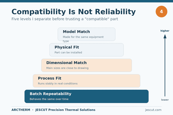
I see “compatible” used in a very broad way in the thermal spray market. Sometimes it means the chamber can be installed into a certain HVOF gun. Sometimes it means the thread or outside shape matches. Sometimes it means the chamber follows a common model name. These checks matter. But they do not prove that the part will run with the same flame stability or the same service life.
Compatibility levels I separate in my review
| Level | What it means | Why it is not enough alone |
|---|---|---|
| Model match | The chamber is made for the same equipment type | The internal quality may still differ |
| Physical fit | The part can be installed | Fit does not prove stable combustion9 |
| Dimensional match | Main sizes are close to drawing | Surface quality may still vary |
| Process fit | The part runs stably in real conditions | This needs consistency and correct settings |
| Batch repeatability | Parts behave the same over time | This depends on manufacturing control |
I always tell customers and engineers that model names can hide important details. Two chambers may both say they fit the same system. One may have a smoother bore. One may have better concentricity. One may have a more stable sealing surface. One may have a small variation near a heat-sensitive area. These differences may not appear during a quick installation check. They may appear only after heat, flow, and powder enter the process.
This matters for procurement. A lower-price part may look compatible on paper. But if its quality is not repeatable, the hidden cost may appear as downtime, rework, coating instability, or frequent replacement.10 I do not say that every alternative part is poor. I also do not say that a branded part never fails. I say that reliability needs a more complete review.
In my manufacturing work, I try to define compatibility with real production control. I want the chamber to match the equipment interface. I also want the inner shape, critical dimensions, surface finish, and batch consistency to stay controlled. I want the user to receive the same behavior part after part. This is more difficult than copying the outside form. It needs stable machining, inspection discipline, and feedback from real use.
So when I analyze a failed chamber, I ask several questions. Was the part only physically compatible? Was it made with stable machining? Did the bore finish match the process need? Did the sealing area sit correctly? Did the same supplier batch show the same behavior? These questions make the analysis more useful and less emotional.
A System-Level View of Combustion Chamber Failure: Material, Process, and Operating Conditions?
I do not like one-answer failure analysis. A combustion chamber works inside a system, so the review should also be a system review.
A system-level combustion chamber failure analysis checks material, machining precision, geometry, surface quality, installation fit, cooling, fuel and oxygen settings, powder behavior, and maintenance history together.11 I use this approach because chamber life depends on both part quality and operating conditions.
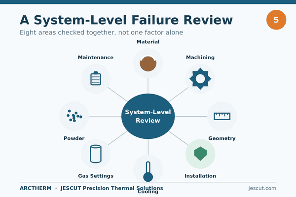
I start with the part, but I do not end with the part. Material matters. Heat resistance, mechanical strength, and manufacturing method may influence service life. But material is not the only variable. A good material can still fail early if the geometry creates a hot spot. A precise chamber can still suffer if cooling is poor. A correct part can still show abnormal wear if the process setting changes.
My practical checklist for system review
| Area | What I review | Why I review it |
|---|---|---|
| Material | Material type and supplier control | Material may affect heat and wear behavior |
| Machining | Critical dimensions and bore quality | Precision may affect flame and fit |
| Geometry | Concentricity and wall consistency | Shape may affect heat distribution |
| Installation | Fit, sealing, and alignment | Poor fit may create uneven heat |
| Cooling | Flow condition and blockage risk | Cooling affects thermal stress12 |
| Gas settings | Fuel and oxygen balance | Settings affect flame temperature |
| Powder behavior | Feed condition and deposit pattern | Powder may change erosion or buildup |
| Maintenance | Cleaning and replacement history | Poor maintenance may hide the root cause |
I use careful language during this review. I say a factor “may contribute to” failure when I do not have confirmed lab data. I say a factor “should be checked together with” other factors when several signs overlap. I do not call a material bad without composition, hardness, metallographic, or other verified evidence. I also do not blame operation as the default answer. I want the analysis to be useful, not defensive.
When I review a chamber from the manufacturing side, I first compare it with the drawing and inspection records. I look at the key sizes. I look at the sealing areas. I look at the bore finish. I look at surface defects that may have started during machining. I also check if the damage location matches a geometry-sensitive zone. If the damage always appears in the same area across several parts, I take that pattern seriously.
Then I ask for operating context if it is available. I ask if the gun was recently rebuilt. I ask if the oxygen or fuel setting changed. I ask if the cooling path was cleaned. I ask if powder type, powder size, or feed behavior changed. I ask if the chamber was installed with the correct mating parts. These questions help me avoid a narrow conclusion.
I believe this system view is the safest way to protect production. It helps equipment users separate product-quality risk from process-condition risk. It helps production engineers find the next inspection step. It helps procurement teams compare suppliers by more than a part number. It also helps manufacturers like me improve the controlled parts of the product, such as machining stability, bore quality, and repeatability.
Conclusion
I analyze combustion chamber failure as a system issue, because material, precision, surface quality, fit, process settings, and maintenance all shape real service life.
"[PDF] Multi-scale modeling and analysis of an industrial HVOF thermal ...", http://pdclab.seas.ucla.edu/Publications/MLi/MLi_PDChristofides_CES_2005_60_Multiscale_Modeling_Analysis_Industrial_HVOF.pdf. Engineering literature on HVOF thermal spraying and high-temperature component failure identifies geometry, surface condition, and process parameters as variables that can influence flow, heat transfer, and component life; this supports the claim contextually rather than proving the cause of any individual chamber failure. Evidence role: general_support; source type: paper. Supports: Manufacturing geometry, surface condition, and operating parameters are recognized contributors to durability and stability in combustion or thermal-spray components.. Scope note: Contextual support; a cited source would not establish root cause for a specific failed chamber without part-specific inspection data. ↩
"11.2.2.2 Combustion Chamber Damage", https://aeroenginesafety.tugraz.at/doku.php?id=11:112:1122:11222:11222. Failure-analysis references for high-temperature combustion components describe cracking, erosion, overheating damage, discoloration, and reduced service life as observable indicators of degradation; the evidence is general and does not identify the root cause in a particular chamber. Evidence role: general_support; source type: institution. Supports: Cracking, erosion, overheating, discoloration, and shortened life are recognized symptoms in high-temperature combustion component degradation.. Scope note: General failure-mode support; symptom lists do not distinguish among material, machining, installation, and operating causes. ↩
"[PDF] THERMAL FATIGUE CRACK GROWTH TESTS AND ANALYSES OF ...", https://repository.lib.ncsu.edu/server/api/core/bitstreams/2ef04fe3-1721-4e9b-a5c1-91a47ebc3b7e/content. Studies of thermal fatigue in combustion liners and other high-temperature components show that temperature gradients, cooling effectiveness, mechanical constraint, and wall geometry influence thermal stress and cracking; this mechanism is applicable by analogy and is not direct proof for the chamber described. Evidence role: mechanism; source type: paper. Supports: Thermal stress and thermal fatigue cracking can be affected by temperature gradients, cooling conditions, constraints, and wall geometry.. Scope note: Mechanistic support by analogy; direct confirmation would require thermal modeling, inspection, or metallurgical analysis of the failed part. ↩
"[PDF] Hot Fire Fatigue Testing Results for the Compliant Combustion ...", https://ntrs.nasa.gov/api/citations/19930001555/downloads/19930001555.pdf. Combustion and heat-transfer literature associates localized hot spots with flame position, flow distribution, and wall-surface conditions that affect boundary-layer behavior and heat transfer; such evidence supports the mechanism but not the specific source of a particular burn mark. Evidence role: mechanism; source type: paper. Supports: Local overheating and burn patterns in combustion hardware can be associated with flame impingement, flow distribution, and surface-condition effects on heat transfer.. Scope note: Contextual mechanism; visual burn marks alone are insufficient to assign cause without operating and inspection data. ↩
"Flow and Heat Transfer over Rough Surfaces", https://cfd.ku.edu/papers/aiaa-2006-0025.pdf. Research on internal flows and combustion hardware shows that geometry, tolerances, and wall roughness can influence flow structure, heat transfer, and flame behavior; the support is mechanistic and does not quantify the effect for this specific chamber design. Evidence role: mechanism; source type: paper. Supports: Dimensional accuracy and surface roughness can affect fluid flow, heat transfer, and combustion stability in internal passages.. Scope note: Mechanistic support; exact sensitivity depends on chamber geometry, flow regime, and operating settings. ↩
"Roughness Effects on Wall-Bounded Turbulent Flows", https://mae.engineering.gwu.edu/roughness-effects-wall-bounded-turbulent-flows. Fluid-mechanics texts and university materials explain that wall roughness alters boundary-layer behavior, friction factor, and turbulence in internal flows; this supports the general mechanism but does not determine the magnitude of disturbance in a particular combustion chamber. Evidence role: mechanism; source type: education. Supports: Wall roughness affects boundary layers, friction, and turbulence in internal flow.. Scope note: General fluid-mechanics support; chamber-specific effects require flow measurements or simulation. ↩
"[PDF] FLAME STABILIZATION AND MIXING CHARACTERISTICS IN A ...", https://seitzman.gatech.edu/MohanBobbaThesis.pdf. Combustion studies show that burner and chamber geometry shape the internal flow field and flame-stabilization region, thereby influencing flame position; this provides mechanistic support rather than direct evidence for the specific chamber design. Evidence role: mechanism; source type: paper. Supports: Burner or chamber geometry influences flow fields and flame stabilization, which can affect flame location.. Scope note: Mechanistic and design-dependent; direct proof would require flame visualization, diagnostics, or validated modeling for the chamber in question. ↩
"Papers for the 6th U.S. National Combustion Meeting", https://par.nsf.gov/servlets/purl/10536023. Studies of coaxial burners and combustion-flow systems indicate that alignment and geometric symmetry affect flow-field symmetry and flame development; this supports the plausibility of centerline effects but is not a direct assessment of the article's chamber. Evidence role: mechanism; source type: paper. Supports: Alignment and concentricity in combustion hardware can affect symmetry of flow and flame development.. Scope note: Contextual support; exact consequences depend on burner design, tolerances, and operating conditions. ↩
"Industry Jobs - Reliability and Maintainability Center", https://rmc.utk.edu/industry-jobs/. Engineering qualification and process-control references distinguish dimensional or interface compatibility from verified functional performance and repeatability; this supports the principle that physical fit alone does not establish stable combustion behavior. Evidence role: general_support; source type: institution. Supports: Functional reliability requires process performance and repeatability checks beyond physical fit or dimensional compatibility.. Scope note: General quality-engineering support; it does not evaluate any particular compatible chamber. ↩
"[PDF] Economics of Manufacturing Machinery Maintenance", https://nvlpubs.nist.gov/nistpubs/ams/NIST.AMS.100-34.pdf. Manufacturing-quality and reliability sources, including public-sector studies of process inefficiency, identify downtime, rework, scrap, and replacement as common costs of poor quality and variability; this supports the economic logic but does not quantify costs for thermal-spray chambers specifically. Evidence role: general_support; source type: government. Supports: Manufacturing quality problems and process variation can produce costs through downtime, rework, scrap, and replacement.. Scope note: Contextual economic support; actual costs require production-specific data. ↩
"Failure Analysis: Definition - Tractian", https://tractian.com/en/glossary/failure-analysis. Authoritative failure-analysis references emphasize that root-cause evaluation should consider material, design, manufacturing, installation, service environment, operating history, and maintenance together; this supports the system-level approach while leaving the specific checklist to the application. Evidence role: expert_consensus; source type: institution. Supports: Failure analysis commonly considers design, material, manufacturing, installation, service environment, operation, and maintenance rather than a single factor.. Scope note: Methodological support; the exact factors must be tailored to the chamber design and available records. ↩
"Structural analysis of thermal fatigue failures on rocket combustion ...", http://ui.adsabs.harvard.edu/abs/1991STIN...9227430H/abstract. Research on cooled combustion liners and rocket or turbine combustion chambers shows that cooling conditions govern wall-temperature gradients, which in turn influence thermal stress and thermal-fatigue behavior; the support is general and design-dependent. Evidence role: mechanism; source type: research. Supports: Cooling changes temperature gradients in combustion components, and those gradients affect thermal stress and fatigue risk.. Scope note: General mechanism; actual stress levels depend on geometry, materials, heat flux, and cooling-flow conditions. ↩